


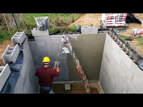
The tank becomes an engineered structure, not just a container
Episode 025 follows the assembly of the water tank and the casting of pillars after early foundation work. A tank integrated into a building is more than storage capacity. It creates hydrostatic loads, needs waterproofing, requires maintenance access and interacts with foundations. The dossier therefore reads this stage as a small hydraulic and structural work. The primary video documents construction; structural approval still belongs to drawings, calculations and verified design assumptions.
Hydrostatic pressure increases with depth
For water at rest, pressure increases approximately according to p = ρgh, where ρ is liquid density, g gravitational acceleration and h depth. The bottom of a tank wall therefore sees greater water pressure than the top. This explains why a reservoir wall cannot be treated like a simple partition. Water depth, geometry, support conditions and reinforcement determine how forces are carried. The formula is used here as a teaching tool, not to size this particular tank without certified dimensions and drawings.
About one tonne per cubic metre makes water structurally important
A cubic metre of water has a mass close to one tonne. Several cubic metres quickly create a load comparable to multiple vehicles. The bearing system must transfer that load to the ground without unacceptable settlement. When a tank sits at the base of a house, the design has to anticipate stored water, tank walls, slabs and whatever structure is carried above.
Pillars: looking vertical is not the same as being adequate
The episode combines tank work with reinforced-concrete pillars. Visible geometry alone cannot establish capacity. Cross-section, longitudinal reinforcement, ties, cover, anchorage, concrete quality, foundation connection and applied load all matter. Site inspection can check plumb, dimensions and reinforcement position, while structural capacity comes from design calculations and drawings. The dossier deliberately avoids the superficial conclusion that a column “looks strong”.
Waterproofing should not hide a structural problem
A tank needs a waterproofing system compatible with its substrate and expected movement. A coating cannot substitute for a sound structure. If cracking comes from excessive movement, covering it may not address the cause. The logical sequence is stable substrate, repair of defects, correct preparation, suitable waterproofing, careful penetrations and verification.
Rainwater systems separate storage, quality and permitted use
French rules distinguish potable water from collected rainwater. A large reservoir is only one element. Permitted uses, labelling, maintenance, backflow protection and possible declarations belong to another layer of the system. Water resilience should therefore be measured not only in litres stored but in demand reduction, sanitary safety, reliability and maintainability.
Overflow and drainage matter when the tank is not simply “full”
A reservoir must handle filling, overflow, draining and maintenance. Overflow should discharge without eroding the surroundings or sending moisture back towards foundations. Draining should be possible without unsafe improvisation. These details are less visually dramatic than casting concrete, yet they strongly influence long-term behaviour.
Maintenance access is part of autonomy
An underground or integrated tank is expensive to alter later. Inspection, cleaning, pumps, filters and sensors need workable access. Saving a small amount of space during construction can create a permanent maintenance penalty. Repairability is part of genuine autonomy: components should be visible, understandable, isolatable and replaceable.
Casting pillars is also about interfaces
Pillars connect foundations to the upper structure. Their axes and levels need to match the geometry of what they will support. A small setting-out error may be repairable, but often generates a chain of packing, plates or local modifications. Before concrete is placed, axes, levels, openings and anchors deserve a dedicated check.
What episode 025 contributes to the series
This stage links two branches of the project: water resilience and load-bearing structure. They cannot be designed independently. A heavy tank affects foundations; pillars affect the tank roof and the house; maintenance access affects layout. The documentary lesson is to identify interfaces before casting elements that will be difficult to change.
Calculation workshop: understand tank loads without mistaking an estimate for structural design
Water is heavy. One cubic metre has a mass of roughly one metric tonne. A 10 m³ tank can therefore contain about 10 tonnes of water before the self-weight of the tank, roof, supports and equipment is added. This first-order calculation explains why columns, bearing areas and the ground beneath them are part of the engineering problem. It does not size a column or prove that a foundation is adequate.
Hydrostatic pressure increases with depth according to p = ρgh. Using ρ ≈ 1,000 kg/m³ and g ≈ 9.81 m/s² gives about 9.8 kPa at one metre depth and about 19.6 kPa at two metres. The wall therefore does not see the same water pressure at the top and at the bottom. A real design must go further and consider geometry, material properties, joints, support conditions, soil action where relevant, filling and emptying phases, cracking control and the applicable design assumptions.
The tank is one component in a water system
Rainwater storage is not defined by storage volume alone. Roof catchment area, rainfall variability, first losses, pre-filtration, inlet arrangement, overflow, access for maintenance, pumping and the separation between non-potable and potable networks all interact. French public guidance treats collected rainwater as non-potable and places restrictions on its uses inside buildings. The educational point is broader than one regulation: physical storage and water quality are different problems. A large tank does not make untreated water suitable for drinking.
A useful water-balance model separates supply and demand. For a simplified roof calculation, annual harvest can be approximated as V = rainfall × effective catchment area × collection coefficient. If a hypothetical 100 m² roof receives 0.7 m of rain over a year and the effective coefficient were 0.8, the gross order of magnitude would be 0.7 × 100 × 0.8 = 56 m³. That number is not a guarantee of usable water: seasonal distribution, tank size, overflow, dry periods, losses and actual consumption determine performance. The calculation is useful because it prevents the tank volume from being chosen in isolation.
Maintenance access is a design requirement
Access should be planned before the roof or surrounding works make the tank difficult to reach. A hatch must allow inspection and the operations the system will need over its life. Filters should be serviceable; overflow and vents should be inspectable; pumps or sensors should be removable; pipe penetrations should remain understandable; and the route for safely draining or isolating equipment should be known. If every repair requires breaking concrete, the system may be technically functional on day one but poorly maintainable.
The same reasoning applies to the pillars shown in the construction sequence. Their performance cannot be inferred from appearance alone. Loads require a continuous path to suitable bearing material, while geometry, reinforcement, concrete quality, curing and connections all matter. The documentary page therefore uses the video to identify the construction sequence but stops short of claiming structural adequacy from images alone.