Course compass
Guiding question : What physically happens between a propellant tank and the thrust leaving the nozzle?
Markers : 📏 MEASURED 📐 CONVENTION 🧮 CALCULATED 🎓 LEARNING ASSUMPTION 🚀 MISSION DATA 🏭 MANUFACTURER DATA ⚠️ APPROXIMATION
Objectives :
- name the main components
- explain why pressure or pumps are required
- follow fuel and oxidizer paths
- understand injector, chamber, and nozzle
- describe a simple start and shutdown sequence
1 — The principle that does not change
A liquid rocket engine carries its own propellants. Fuel and oxidizer are stored separately, fed into a chamber, mixed, reacted, and converted into hot gas accelerated through a nozzle.
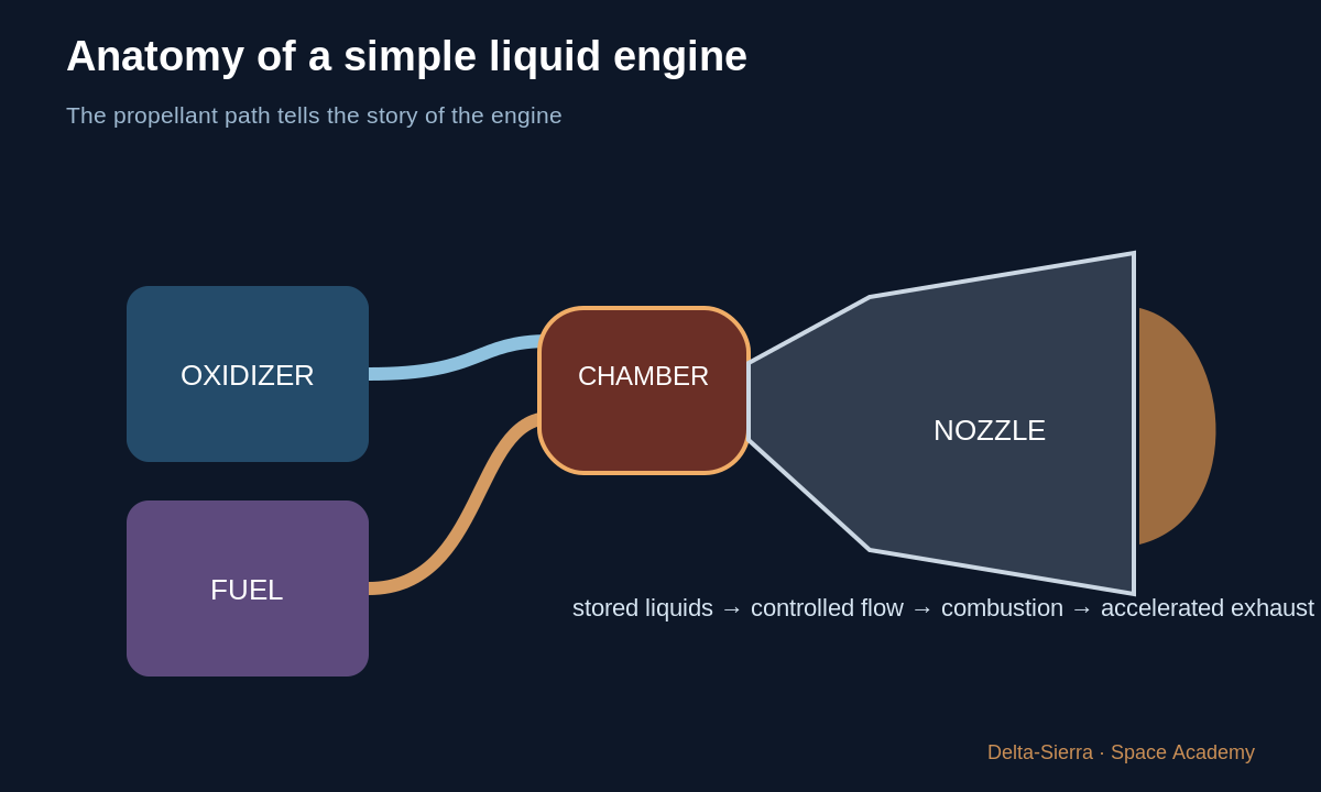
That is why a rocket can work in vacuum: it does not wait for atmospheric oxygen.
2 — Tanks are more than containers
Propellants may be cryogenic, toxic, very cold, reactive, or pressurized. Tanks must withstand pressure, temperature, acceleration, and vibration while remaining light.
3 — Why not just let the liquids flow?
The combustion chamber operates at elevated pressure. To inject liquid into it, upstream pressure must be high enough. Two pedagogical approaches are tank pressurization and pump/turbopump feed.
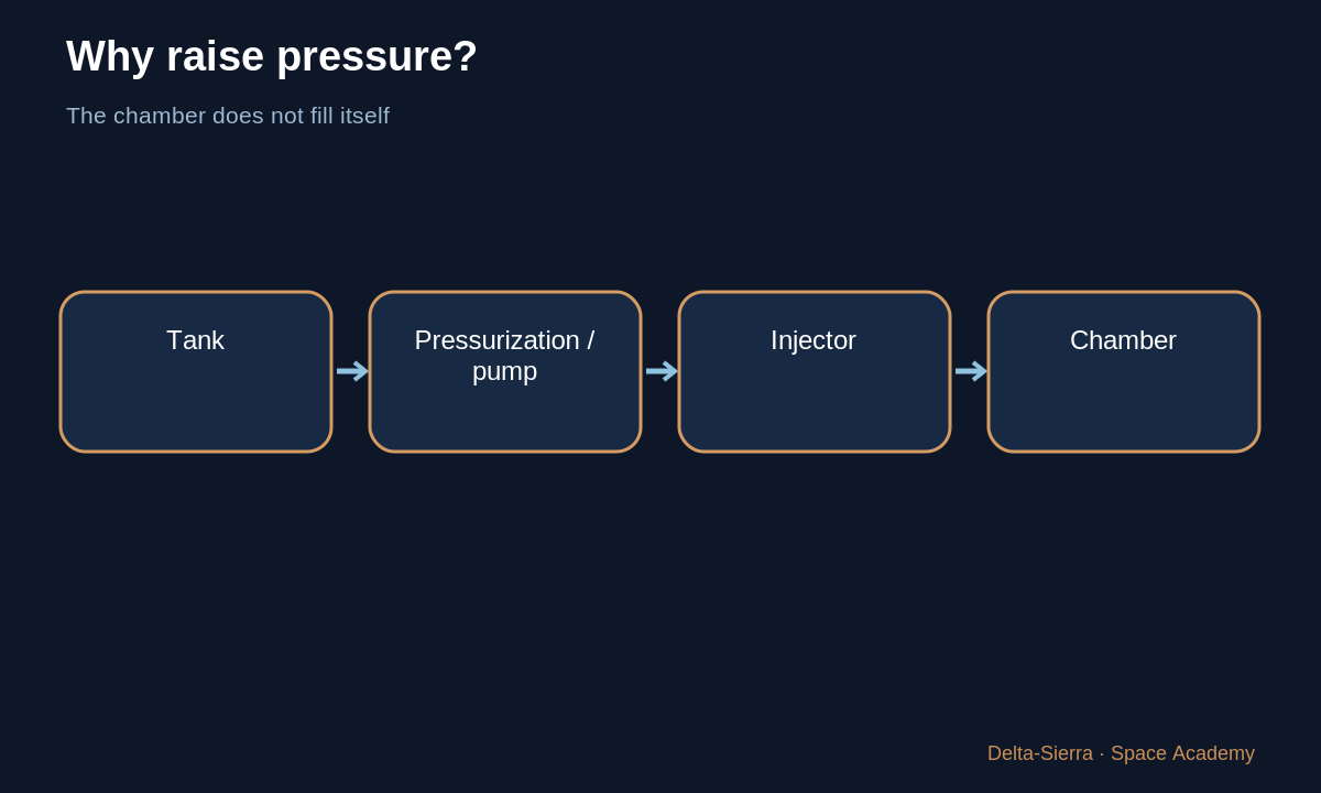
A turbopump combines a turbine receiving power from hot or energetic gas and a pump that raises liquid pressure.
4 — Valves: decide when and how much fluid can pass
A valve opens, closes, or modulates a passage. It must move on command, seal when required, and avoid dangerous failure states. Valves participate in engine sequencing and flow control.
5 — Injector: mixing begins here
The injector distributes fuel and oxidizer into the chamber to promote rapid, controlled mixing. Poor distribution can create hot spots, incomplete combustion, or instability.
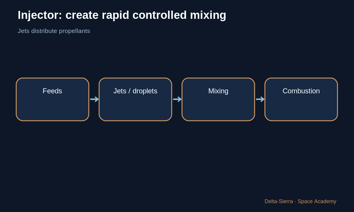
The injector is therefore not merely a large shower head; its geometry is part of combustion dynamics.
6 — Combustion chamber: pressure, heat, stability
Reaction produces very hot high-pressure gas. The chamber must remain mechanically intact and combustion must remain stable. Correct average thrust does not guarantee absence of destructive oscillations.
7 — Why does the engine not melt immediately?
One common method is regenerative cooling: cold propellant passes through channels around chamber and nozzle, absorbs heat, and then enters the engine cycle.
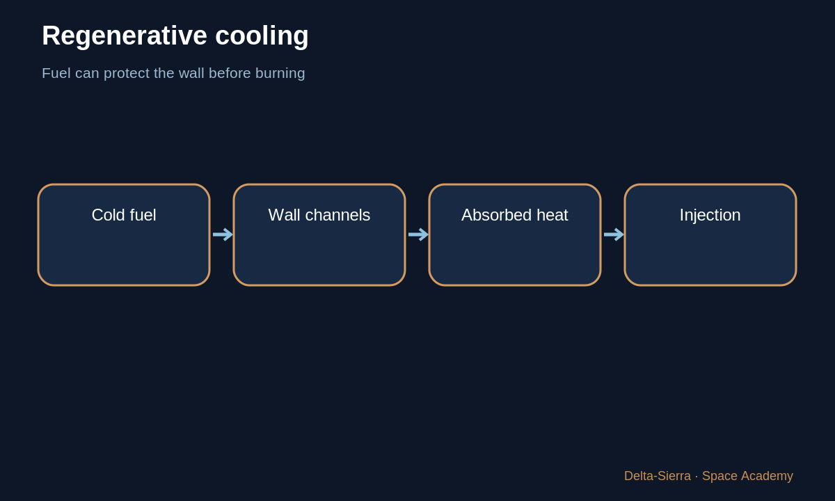
The wall becomes structure, heat exchanger, and boundary between extremely hot gas and coolant.
8 — Throat and nozzle: convert pressure and heat into velocity
The smallest section is the throat. Under appropriate conditions, flow reaches Mach 1 there. The diverging nozzle then converts part of gas energy into directed exhaust velocity.
Nozzle geometry therefore affects mass flow, exit pressure, exit velocity, and thrust.
9 — Engine start is choreography
Opening everything at once can create mixture in the wrong place, pressure spikes, or unstable ignition. Engines use controlled sequences: condition circuits, establish pressure, spin turbomachinery, ignite, open progressively, and ramp to mainstage.
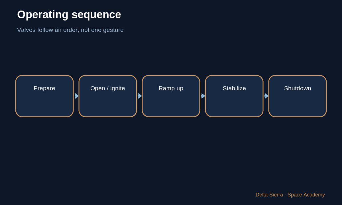
Shutdown is also sequenced to avoid reactive mixtures or damaging temperatures.
10 — History: increasing sophistication, stable core principle
Pioneer engines, V-2, Saturn V F-1, J-2, European Vulcain/Vinci, and modern methane engines differ greatly. Yet the core chain remains: store, feed, mix, react, accelerate, control.
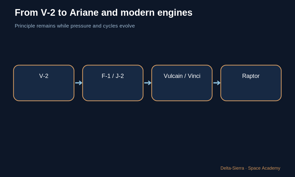
Technical history becomes understandable as successive generations pursue performance, control, life, restart, and reuse while obeying the same physical constraints.
Exercises and solutions
Exercise A — put parts in order
Order nozzle, tank, injector, chamber, pump.
Exercise B — pressure
Why is gravity feed insufficient for a high-pressure chamber?
Challenge — reduced flow
A pump spins but flow falls. Name three possible cause families.