Course compass
Guiding question : How can internal pressure give a first thickness estimate, and why does the real part require much more analysis?
Evidence tags : 📏 MEASURED · 📐 CONVENTION · 🧮 CALCULATED · 🎓 LEARNING ASSUMPTION · 🚀 MISSION DATA · 🏭 MANUFACTURER DATA · ⚠️ APPROXIMATION
Objectives :
- read hoop stress logic
- use a thin-wall learning model
- explain every symbol and unit
- understand allowable stress and margin
- identify limits: buckling, welds, dynamics, cryogenics
1 — First question: what is trying to tear the tank apart?
Internal pressure pushes on every wall. In a thin cylinder it tends to open the vessel around its circumference, so the material must develop an opposing stress.
The larger the radius, the larger the global force created by the same pressure. A giant tank therefore cannot be naively scaled from a small bottle.
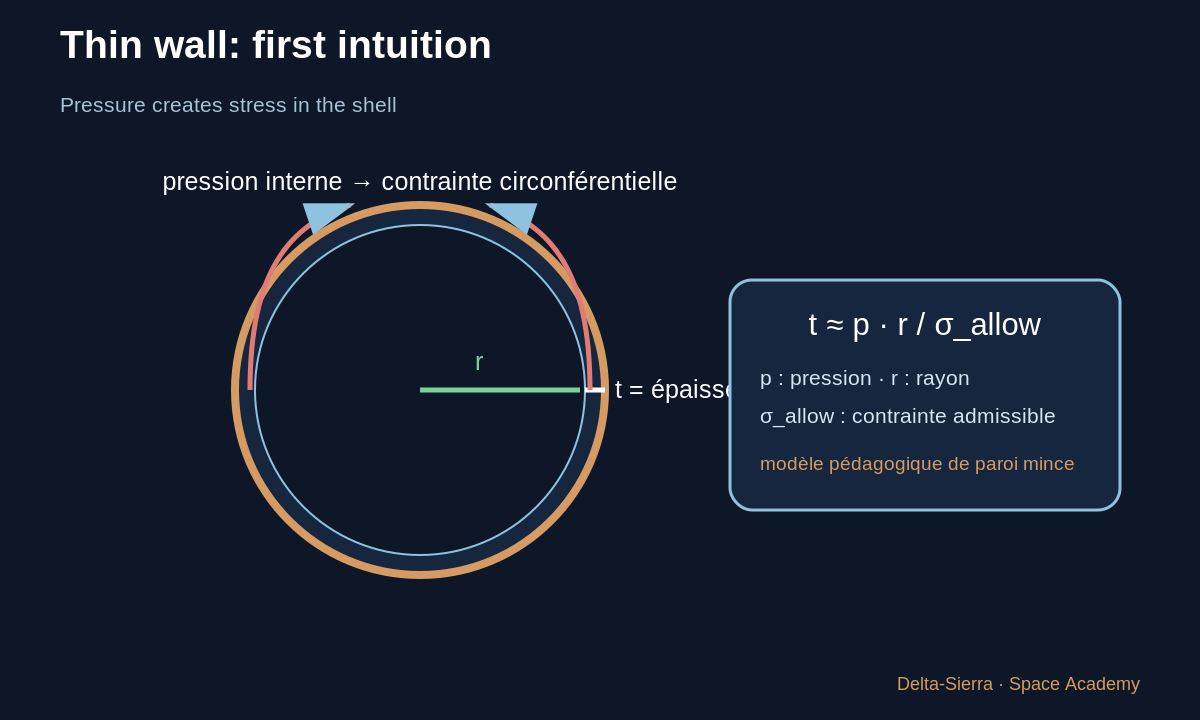
2 — A first learning model: t ≈ p·r / σ_allow
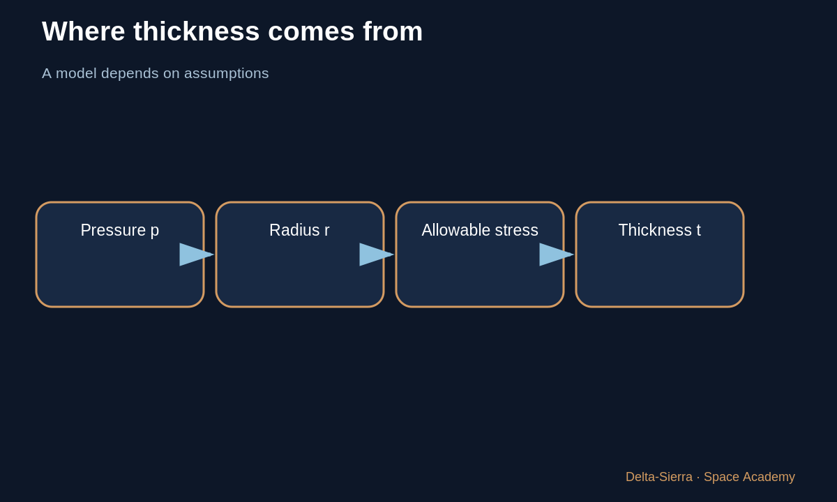
t is wall thickness. p is relative internal pressure. r is radius. σ_allow — “sigma allowable” — is the stress level our simplified model allows.
The thin-wall equation is not a manufacturing recipe. It exposes dependencies: double p and t rises; double r and t rises; increase allowable material stress and the theoretical thickness can fall.
3 — Deliberately simple example
LEARNING ASSUMPTION: p = 0.30 MPa, r = 2.0 m, σ_allow = 120 MPa. Both pressure and stress are in megapascals, so the ratio is dimensionally consistent.
t ≈ (0.30 × 2.0) ÷ 120 = 0.005 m = 5 mm. This is NOT a recommended flight wall thickness. It only demonstrates the model logic.
4 — Why the real tank does not stop at “5 mm”
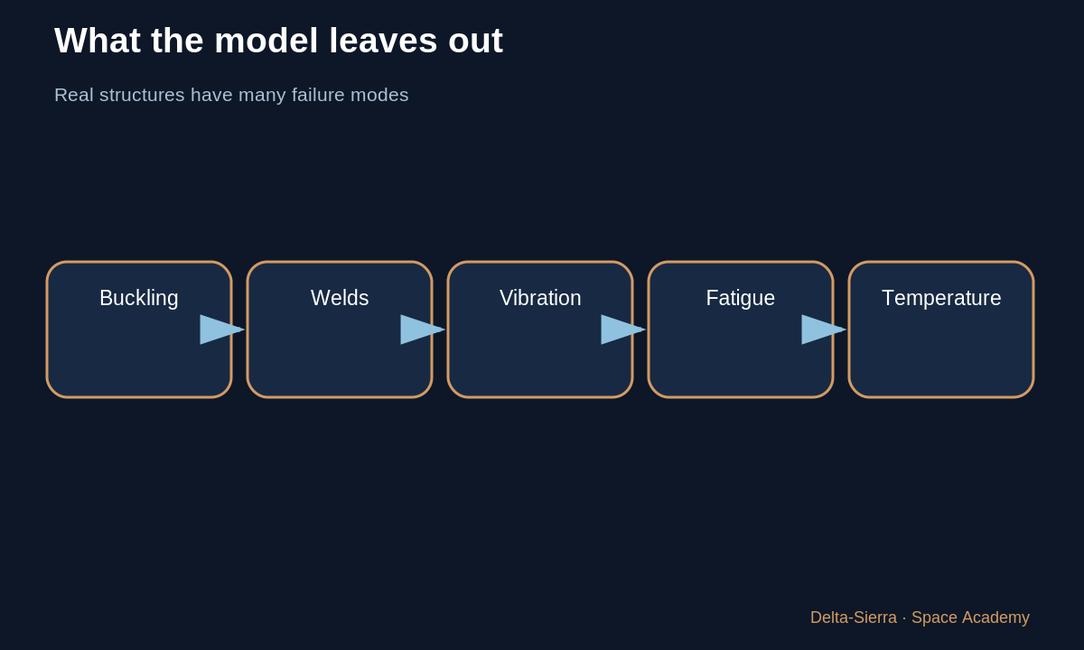
The structure sees longitudinal acceleration, bending, vibration, aerodynamic loads, geometric imperfections, stress concentrations, pressure cycles, and manufacturing variation. A very thin shell can buckle in compression before the material reaches tensile failure.
Domes, joints, welds, openings, supports, and thrust-transfer regions experience different stress states. Real launchers therefore use locally tailored and verified structure.
5 — Why allowable stress is below rupture strength
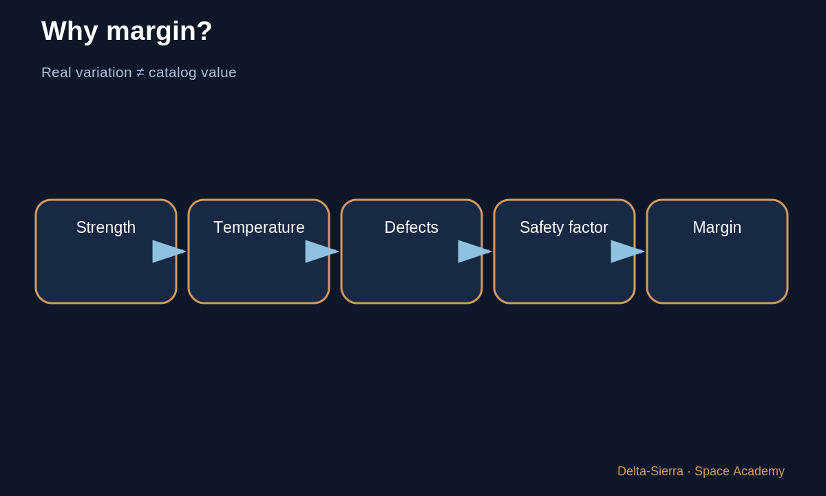
Certified hardware is not designed to reach theoretical rupture on every flight. Engineers apply safety factors, margins, temperature effects, and material/process scatter.
An allowable value must be tied to a standard, heat treatment, load type, and temperature. Copying a strength number from the internet without those conditions is unsafe.
6 — Cryogenic temperature and manufacturing change the real material
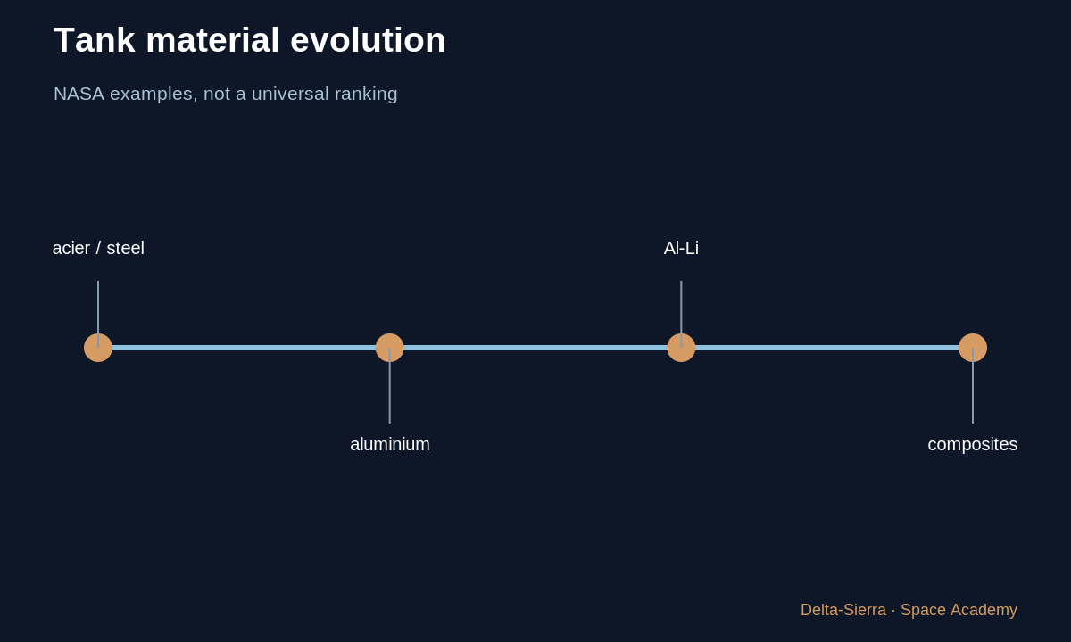
NASA studied weldable aluminum alloys specifically for cryogenic booster tankage. More recently Al-Li 2195 has been developed to reduce mass while retaining high mechanical properties.
NASA also states that required thickness depends on the actual configuration. A material that looks “better” on a datasheet may lose its advantage if forming, welding, inspection, or cost become unacceptable.
7 — The engineering habit
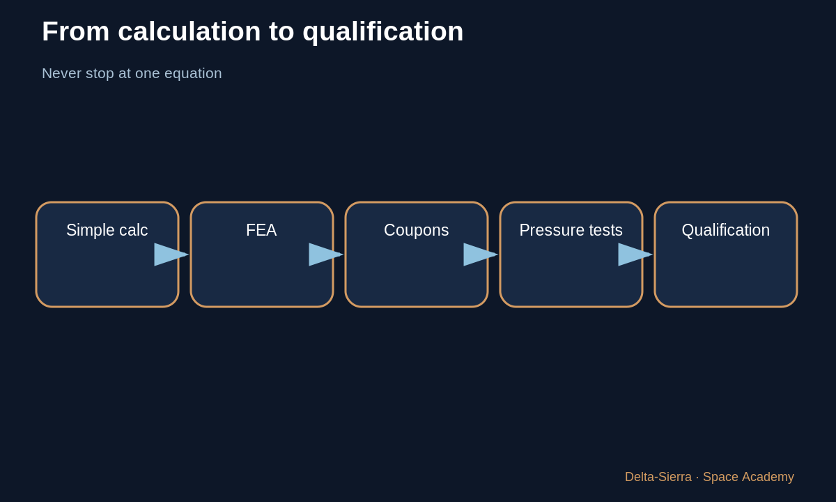
A simple equation is a compass. Then come load models, finite-element analysis, material tests, welded coupons, pressure testing, dynamics, and qualification.
The real question is not “what thickness do I choose?” but “which failure modes must I prevent, with what verified margins?”
8 — Wall thickness is not one number across a rocket
Loads are not uniform even in a cylindrical tank. Joints, openings, attachments, domes and engine-adjacent zones can concentrate stress. Internal pressure is only one load: acceleration, bending, vibration, temperature and ground handling also matter.
That is why the thin-wall relation in this lesson is only a way to understand trends. It cannot design flight hardware. Real work identifies load cases, builds models, checks possible failure modes and confronts those models with tests. The better question is not “what thickness do I need?” but “what mechanisms can remove the function, and what margin exists against each one?”
9 — Mass saved, robustness lost: the permanent trade
Reducing wall thickness by a few percent can save substantial mass over a large area, but only if the component remains manufacturable, inspectable and tolerant enough to defects. Adding thickness everywhere “for safety” increases vehicle mass, increases the mass that must be accelerated and may require more propellant.
Space engineering therefore rarely seeks an absolute maximum. It seeks a verified compromise. The same lesson will reappear in thermal design, redundancy, power and life support: margin has a cost, and the cost of margin can create a new risk.
8 — Three complete examples: see the model’s sensitivity
Example A — deliberately simple case
Use p = 0.30 MPa, r = 2.0 m, and σ_allow = 120 MPa. The teaching relation gives t ≈ (0.30 × 2.0) ÷ 120 = 0.005 m, or 5 mm. Pressure is multiplied by radius because, in this thin-cylinder model, a larger radius gives pressure more geometric leverage in producing hoop stress. Division by σ_allow represents the fact that a greater allowable stress can carry the same simplified load with less section.
🎓 TEACHING ASSUMPTION: these values illustrate dependency; they are not a flight design.
Example B — double the radius
Keep p = 0.30 MPa and σ_allow = 120 MPa but take r = 4.0 m. Then t ≈ (0.30 × 4.0) ÷ 120 = 0.010 m, or 10 mm. Radius doubles and this model’s result doubles. Scaling a tank is therefore not just enlarging a drawing.
🧮 CALCULATED: 10 mm is a simplified-model result, not a certified wall thickness.
Example C — higher allowable stress
Return to p = 0.30 MPa and r = 2.0 m but use σ_allow = 200 MPa. t ≈ 0.60 ÷ 200 = 0.003 m, or 3 mm. The theoretical thickness falls because the denominator rises. Yet a stronger material may be harder to weld or less attractive at cryogenic temperature, so this equation cannot select the material by itself.
⚠️ APPROXIMATION: real design also considers buckling, welds, dynamic loads, fatigue, and manufacturing.
Inverse calculation — fixed thickness
With p = 0.30 MPa, r = 2.0 m, and t = 6 mm = 0.006 m, solve for σ_allow: σ_allow ≈ p·r/t = (0.30 × 2.0) ÷ 0.006 = 100 MPa. “Isolating” σ_allow simply means rearranging the relationship so that the unknown stands alone.
The inverse calculation checks conceptual consistency; it still does not authorize fabrication.
Exercises and answers
Pressure sensitivity
If p doubles in the same model while everything else stays fixed, what happens to t?
Radius sensitivity
Same pressure and material, radius divided by two.
Trap
Why can the 5 mm result not become a manufacturing drawing?