Course compass
Guiding question: What must the chamber accomplish between propellant injection and nozzle entry?
Markers: 📏 MEASURED · 📐 CONVENTION · 🧮 CALCULATED · 🎓 TEACHING ASSUMPTION · ⚠️ APPROXIMATION
- distinguish chamber and nozzle
- understand flow and energy
- introduce cooling
- introduce combustion stability
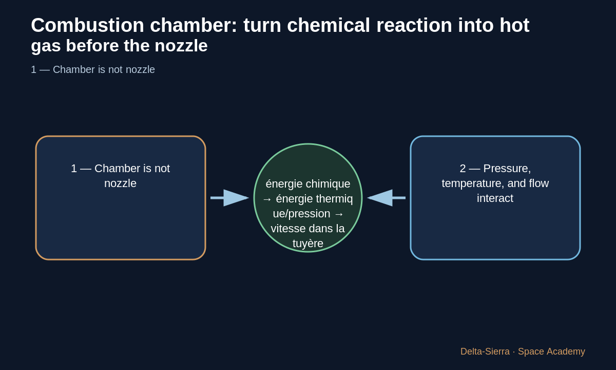
1 — Chamber is not nozzle
The chamber provides volume where mixing and reaction release energy and create hot, high-pressure gas. The nozzle then turns part of this energy into directed speed.
Separating functions explains why geometry, materials, and cooling differ.
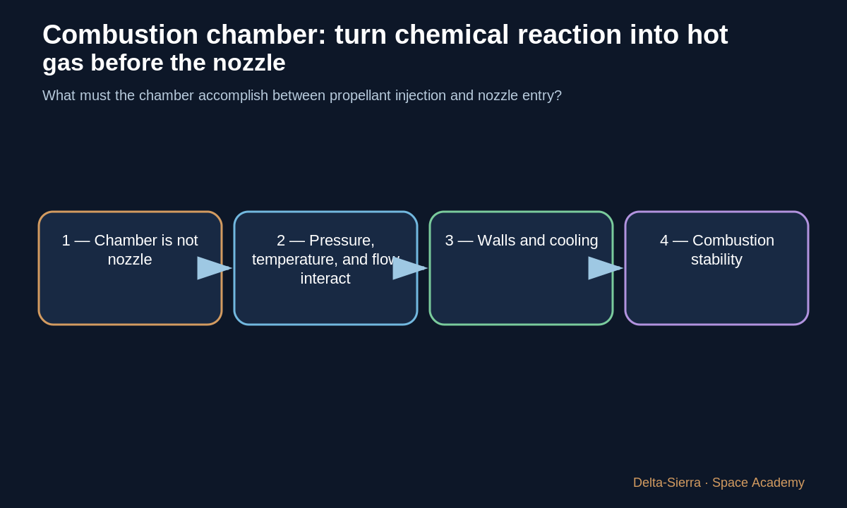
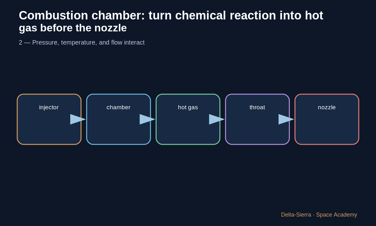
2 — Pressure, temperature, and flow interact
The engine passes mass flow while maintaining chamber conditions compatible with its cycle. Gas properties and throat geometry matter strongly.
One equation cannot describe all combustion phenomena.
3 — Walls and cooling
The wall receives intense heat flux. Liquid engines may route propellant through cooling channels before injection: regenerative cooling.
Materials must balance strength, conductivity, thermal fatigue, and manufacturability.
4 — Combustion stability
A chamber can develop oscillations coupled to injection, acoustics, and heat release. F-1 history shows the problem required testing and injector modifications.
Good combustion is more than “it ignites”.
Three complete examples: change one assumption to understand
Before each calculation, identify where every number comes from and whether it is measured, conventional, assumed, or calculated.
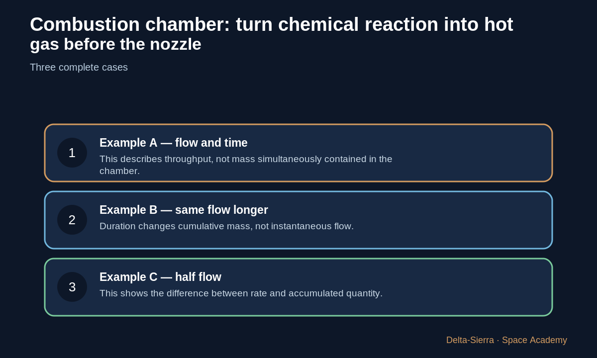
Example A — flow and time
Conceptual total flow 40 kg/s for 2 s: 80 kg passes through.
This describes throughput, not mass simultaneously contained in the chamber.
Example B — same flow longer
40 kg/s for 5 s: 200 kg has passed through.
Duration changes cumulative mass, not instantaneous flow.
Example C — half flow
20 kg/s for 5 s: 100 kg.
This shows the difference between rate and accumulated quantity.
Inverse calculation
If 200 kg passed in 5 s at constant average flow, flow=200/5=40 kg/s.
Common trap and result check
Trap: inferring real chamber pressure from flow alone. Geometry, thermodynamics, throat, cycle, and losses are missing.
In a real engine system, a conceptual result must later be checked against fluid properties, margins, tests, and qualification.
Exercises and answers
Function
Explain the function of each block without jargon.
Sensitivity
Halve one assumption and predict the consequence.
Limit
Name one reason the teaching model is insufficient for a real engine.