Course compass
Guiding question : How can a tiny electrical signal command movement of an engine producing enormous thrust?
Evidence tags : 📏 MEASURED · 📐 CONVENTION · 🧮 CALCULATED · 🎓 LEARNING ASSUMPTION · 🚀 MISSION DATA · 🏭 MANUFACTURER DATA · ⚠️ APPROXIMATION
Objectives :
- separate command power from mechanical power
- read force/torque/lever arm
- understand hydraulic amplification
- understand holding load
- see why NASA uses 3D TVC load models
1 — The signal does not supply all the energy
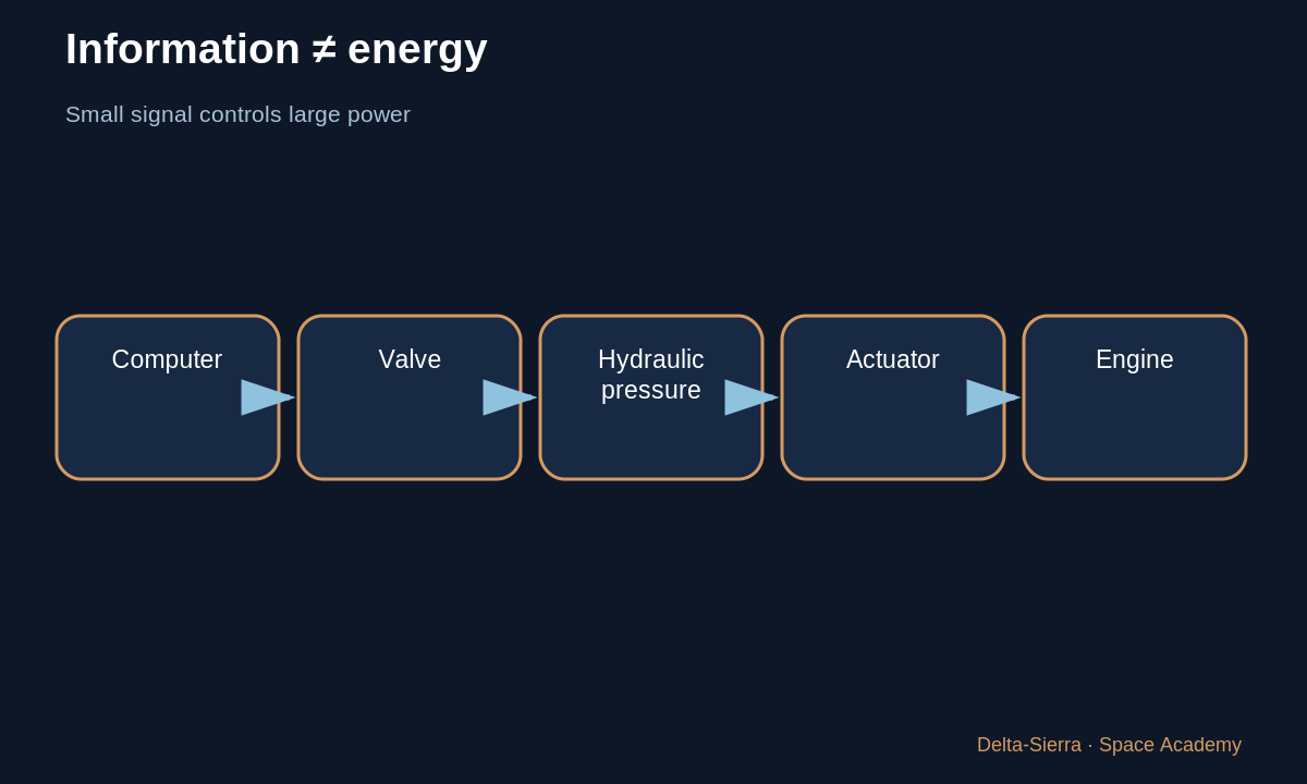
A flight computer may output a low-power electrical signal. That signal commands a valve or actuator motor which controls a much larger mechanical energy source.
Information and energy therefore come from different places: a small command can control high hydraulic power.
2 — Force, torque, and lever arm
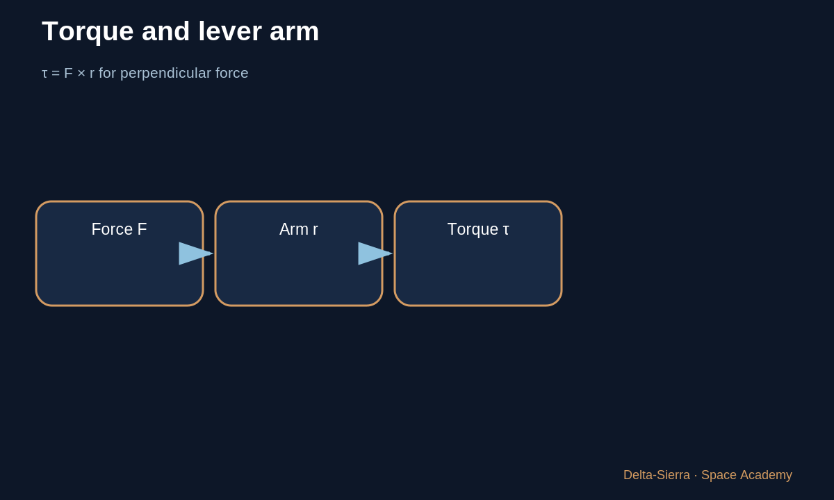
A force applied far from an axis creates more moment than the same force near the axis. In a simple perpendicular model: τ = F × r.
τ is “tau”, torque in newton-meters. F is force in newtons; r is distance in meters.
3 — Learning example
LEARNING ASSUMPTION: a mechanism must deliver 120,000 N·m of torque and its effective actuator lever arm is 1.5 m. Ideal force F ≈ τ/r = 120,000 / 1.5 = 80,000 N.
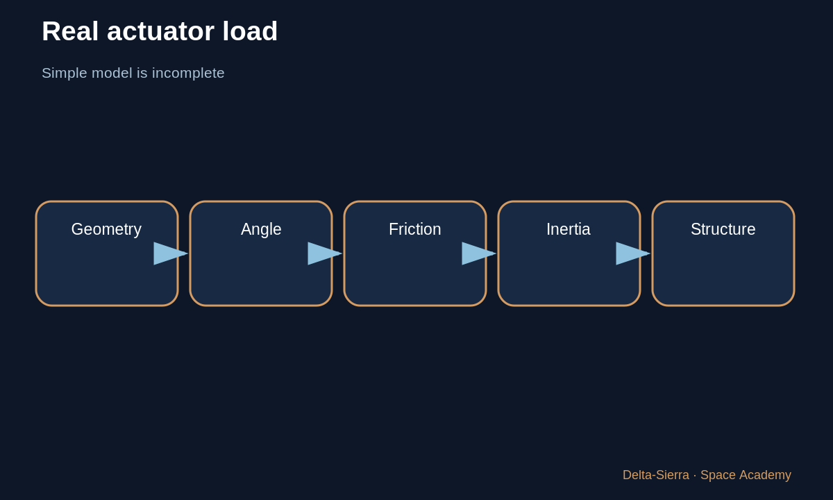
This is not a Vulcain or Falcon load. Real geometry includes angle, two axes, friction, flexibility, inertia, transients, and safety factors.
4 — Why hydraulics can move a large engine
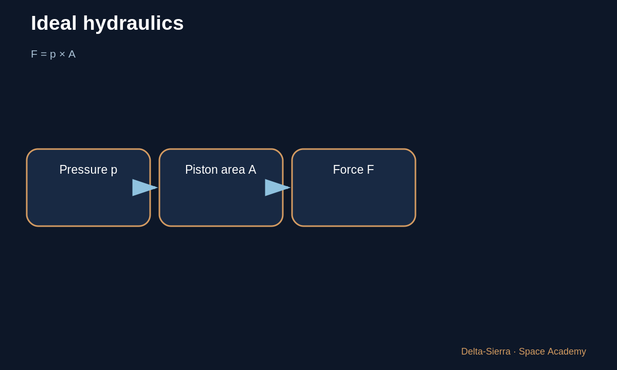
A pump pressurizes fluid. A valve controls which side of a piston receives that fluid. Pressure acting over piston area produces force: F = p × A in the ideal model.
A small valve motor can therefore control hydraulic flow that creates far greater force. ESA describes this principle for Vulcain 2.1 TVC.
5 — Holding matters as much as moving
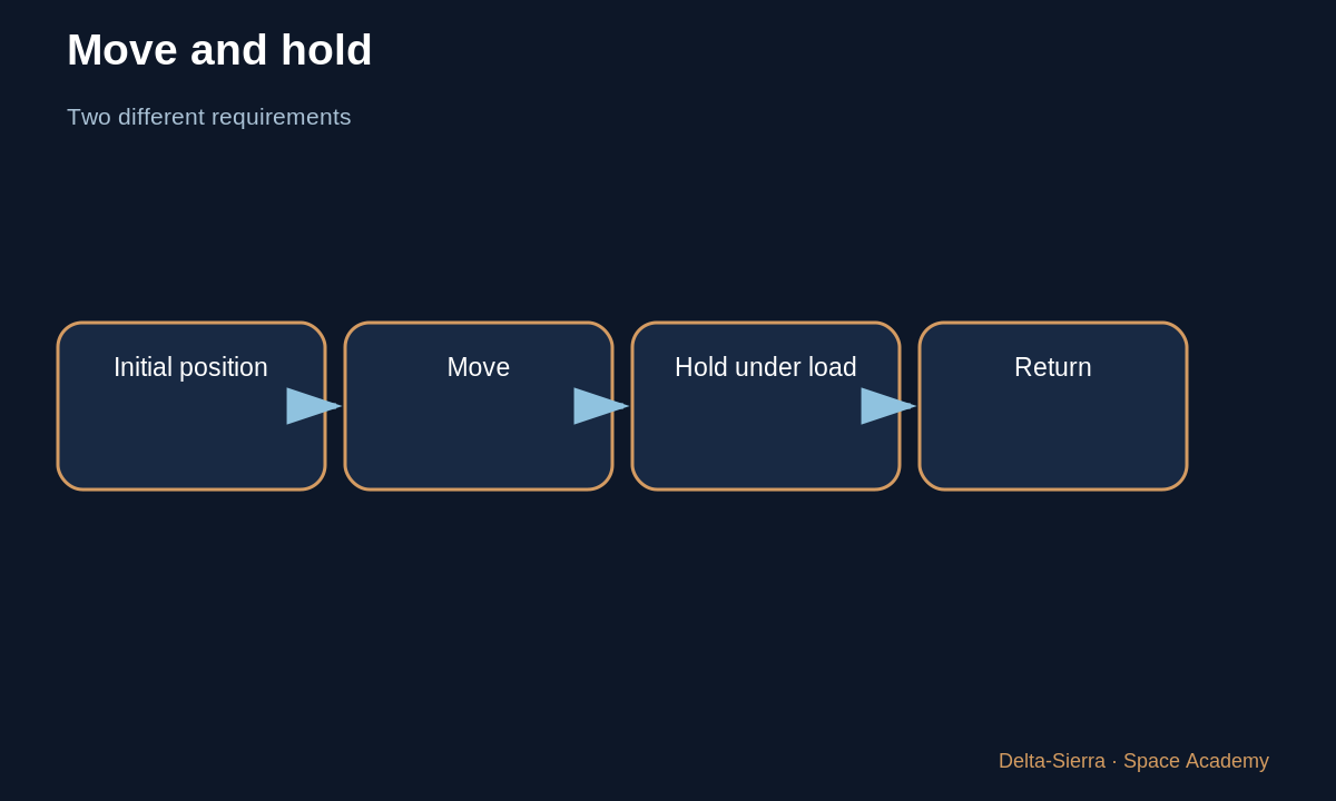
The actuator must resist forces that try to move the engine away from commanded position. NASA publishes methods for calculating reaction force along the actuator line of action during holding.
Gimbal friction and structural response can change under real thrust load; hot-fire tests can reveal differences from laboratory models.
6 — Mechanical control meets software control
Software must respect actuator speed, travel, and force limits. An impossible mechanical command cannot be executed even if the algorithm asks for it.
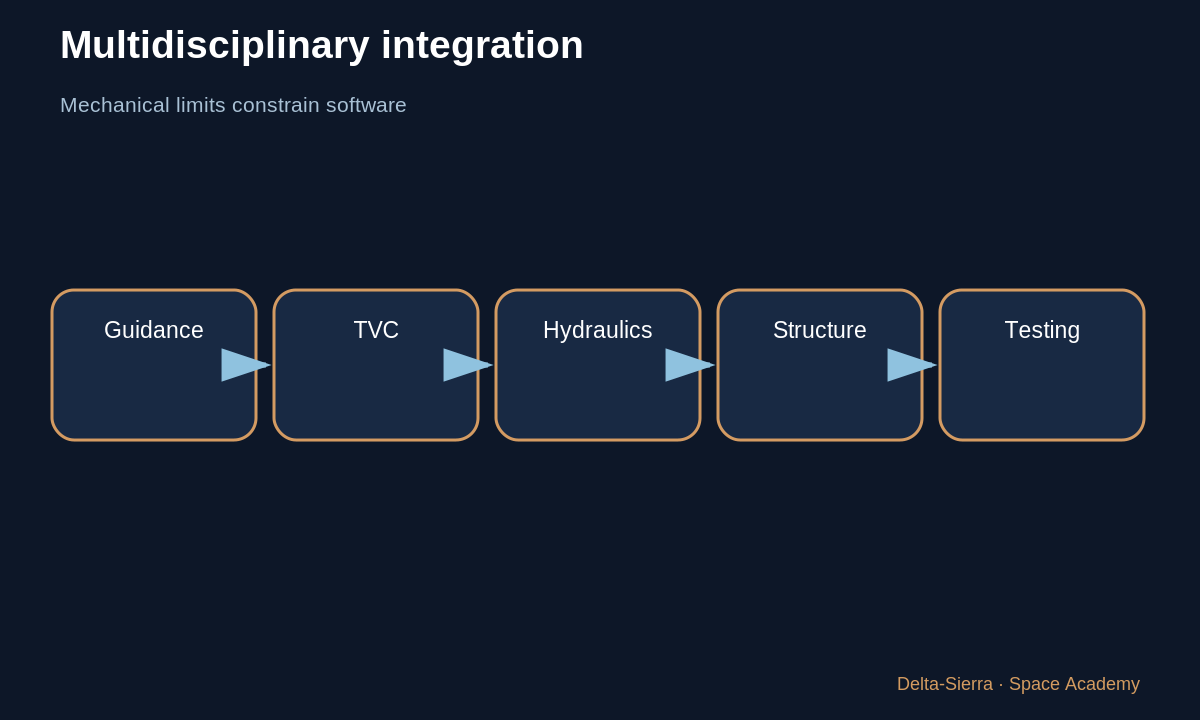
Integrated design therefore connects guidance, vehicle dynamics, TVC, hydraulics/electromechanics, structure, and sensing.
7 — The actuator must survive a changing in-flight load
Torque on a gimbaled engine is not determined by average thrust alone. Geometry, acceleration, vibration, structural flexibility and friction can change the load. A single force value is rarely sufficient; engineers build operating envelopes and search for the governing case.
NASA TVC load work illustrates this approach: the gimbaled engine is modeled mechanically and several contributions are combined to estimate actuator-line loads. Space Academy keeps the reasoning while deliberately not reproducing proprietary parameters of an operational vehicle.
8 — Hydraulic or electric power must also be budgeted
Moving an engine consumes energy. That energy comes from a hydraulic, electromechanical or other actuation architecture that has its own mass, efficiency, temperature and failure modes. A more powerful actuator is therefore never free: the vehicle must generate, distribute and reject the heat associated with that power.
This connects TVC to systems engineering. A guidance decision becomes a mechanical requirement; the mechanical requirement becomes a power requirement; the power requirement becomes a demand on electrical or hydraulic and thermal systems. Following chains like this is how a rocket becomes understandable as a whole.
8 — Three complete examples: torque, lever arm, and force
Example A — reference case
TEACHING ASSUMPTION: required torque τ = 120,000 N·m and lever arm r = 1.5 m. From τ = F × r, solve F = τ/r = 120,000 ÷ 1.5 = 80,000 N. Division answers the question “what force at this lever arm creates the requested torque?”.
🎓 TEACHING ASSUMPTION: these numbers do not describe a specific flight actuator.
Example B — half the lever arm
Keep τ = 120,000 N·m but reduce r to 0.75 m. F = 120,000 ÷ 0.75 = 160,000 N. Halving the lever arm doubles the required force in this model.
🧮 CALCULATED: 160,000 N, twice the first result.
Example C — double the torque
With r = 1.5 m but τ = 240,000 N·m, F = 240,000 ÷ 1.5 = 160,000 N. Doubling requested torque doubles required force. Real actuators also face speed, acceleration, friction, compliance, backlash, and transient loads.
⚠️ APPROXIMATION: static torque is only the first layer.
Inverse calculation — what lever arm?
Suppose τ = 120,000 N·m and conceptual force is limited to F = 60,000 N. Then r = τ/F = 120,000 ÷ 60,000 = 2 m. This does not mean an actuator can simply be moved to 2 m; structure, stroke, joints, and geometry constrain the architecture.
The inverse calculation explores a trade, not a flight design.
Exercises and answers
Force
τ = 60,000 N·m, r = 2 m. Ideal force?
Hydraulics
p = 20 MPa and A = 0.002 m², ideal model.
Limit
Why can these two exercises not be combined into a real actuator design?