Course compass
Guiding question : How can a vehicle redirect enormous thrust without using the whole rocket as a rudder?
Evidence tags : 📏 MEASURED · 📐 CONVENTION · 🧮 CALCULATED · 🎓 LEARNING ASSUMPTION · 🚀 MISSION DATA · 🏭 MANUFACTURER DATA · ⚠️ APPROXIMATION
Objectives :
- define TVC and gimbal
- connect thrust angle to torque
- understand actuator roles
- compare hydraulic and electromechanical actuation
- identify gimbal structural loads
1 — TVC: control the thrust vector direction
TVC means Thrust Vector Control. Instead of changing only force magnitude, the system changes its direction slightly.
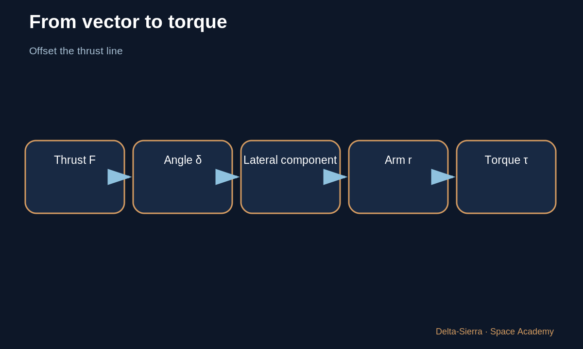
When the thrust line no longer passes through the center of mass, it creates torque that rotates the vehicle.
2 — Why a few degrees can be enough
Engine force is enormous and the lever arm to the center of mass can be several meters. A small lateral component can therefore create a large moment.
In a simple model the lateral component is about F·sin(δ), where δ is gimbal angle. For small angles sin(δ) is small, but F can be huge.
3 — Learning torque example
LEARNING ASSUMPTION: F = 1,000 kN, δ = 2°, effective lever arm r = 15 m. sin(2°) ≈ 0.0349. Lateral force ≈ 1,000,000 × 0.0349 = 34,900 N.
Simplified moment τ ≈ r × F_lat = 15 × 34,900 ≈ 523,500 N·m. This demonstrates sensitivity; it is not a real launcher load model.
4 — What physically moves the engine?
An actuator converts command into mechanical motion. Energy may be hydraulic or electromechanical. ESA describes Vulcain hardware where small torque motors control hydraulic valves, then fluid moves the much larger engine.
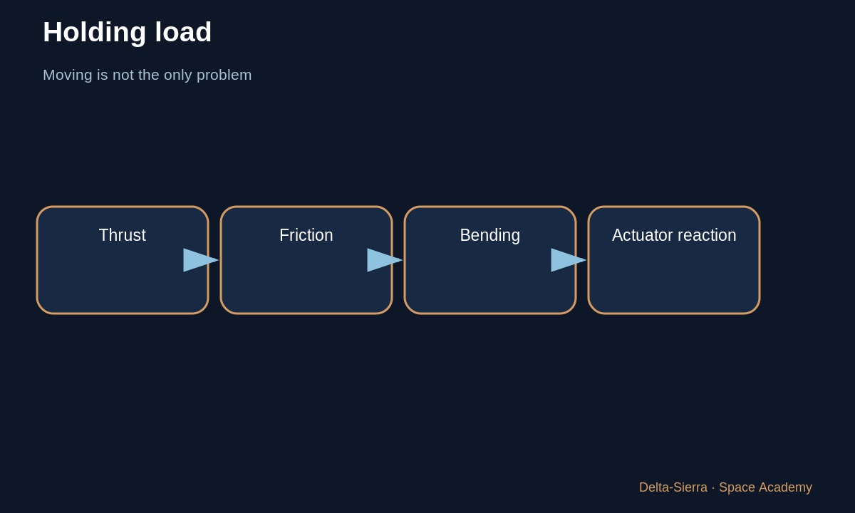
The system must both move and hold the engine against thrust loads, acceleration, structural bending, and gimbal friction.
5 — Two axes: pitch and yaw
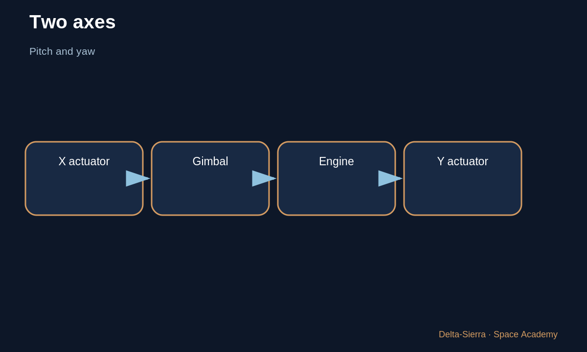
Two actuators in different directions allow rotation about two axes. NASA documents SLS architectures using actuators and a gimbal block/bearing.
Control must also coordinate multiple engines; moving every engine identically is not always optimal on multi-engine vehicles.
6 — Why the real problem requires a 3D model
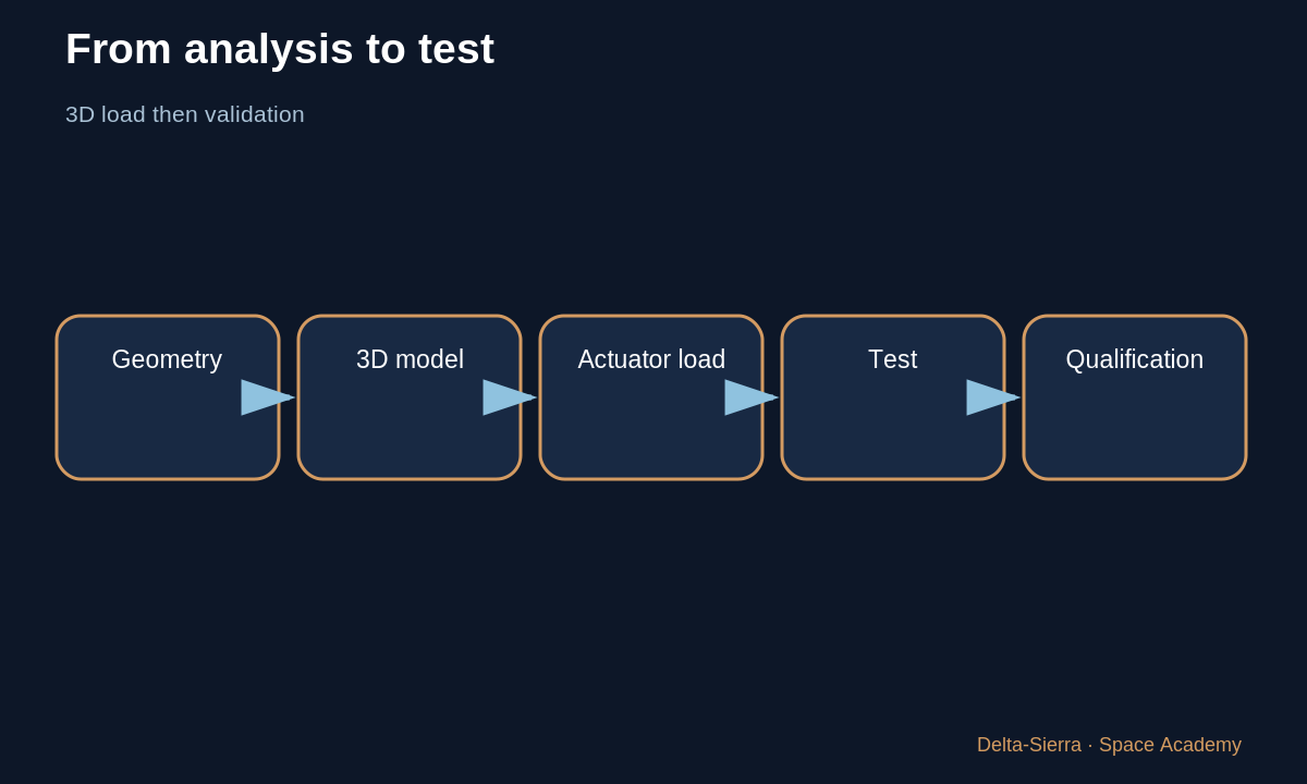
Actuator load depends on real geometry, angle, pivot position, friction, and dynamic forces. NASA publishes modern 3D TVC load-prediction methods.
The course equation shows the principle; certification requires complete mechanical models and loaded testing.
7 — Turning a small engine angle into vehicle rotation
Gimbaling an engine does not instantly rotate the whole rocket. Thrust creates a moment about the center of mass; that moment creates angular acceleration; attitude begins to change; sensors measure that change; then command changes again. There is a time chain from command to mechanical action to vehicle response.
This is why a simple arrow diagram is useful for intuition but not enough for control. Mass, moment of inertia, engine location, structural flexibility and actuator speed all change the response. Thrust-vector control is a dynamics problem, not merely a geometry problem.
8 — Actuator saturation matters as much as the control law
Software can ask for a correction that mechanics cannot provide: too much angle, too much rate or too much load. This is saturation. A sound control design must know those limits instead of assuming an ideal actuator.
Mechanics, electronics and software must therefore be designed together. A brilliant guidance equation is useless if it requires impossible motion. Oversizing the actuator also adds mass, power and complexity. The compromise has to be closed at system level.
Exercises and answers
Component
F = 500 kN and sin δ = 0.02. Simplified lateral component?
Torque
10,000 N with an 8 m lever arm.
Limit
Why does torque not directly give vehicle rotation angle?