Course compass
Guiding question : When the launcher departs from command, who senses the error, who decides, and what moves the engine?
Evidence tags : 📏 MEASURED · 📐 CONVENTION · 🧮 CALCULATED · 🎓 LEARNING ASSUMPTION · 🚀 MISSION DATA · 🏭 MANUFACTURER DATA · ⚠️ APPROXIMATION
Objectives :
- separate command from measurement
- calculate signed error
- understand a learning proportional controller
- connect sensors, computer, and actuator
- understand why real control laws are richer
1 — A launch vehicle is not hand-steered like a car
During fast flight phases, the flight computer automatically executes guidance and control loops. Inertial sensors measure rotation and acceleration; state estimators reconstruct vehicle state.
Humans define mission, limits, and procedures, but they do not manually move a stick every tenth of a second to hold the launcher axis.
2 — Define the error
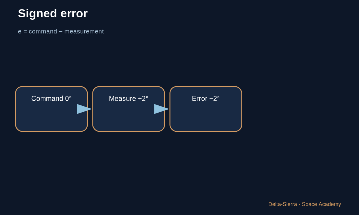
Assume target attitude 0° on one axis and measured attitude +2°. Define error = command − measurement. Then e = 0 − 2 = −2°.
The negative sign does not mean “bad result”; it indicates correction direction under our convention.
3 — A first proportional controller
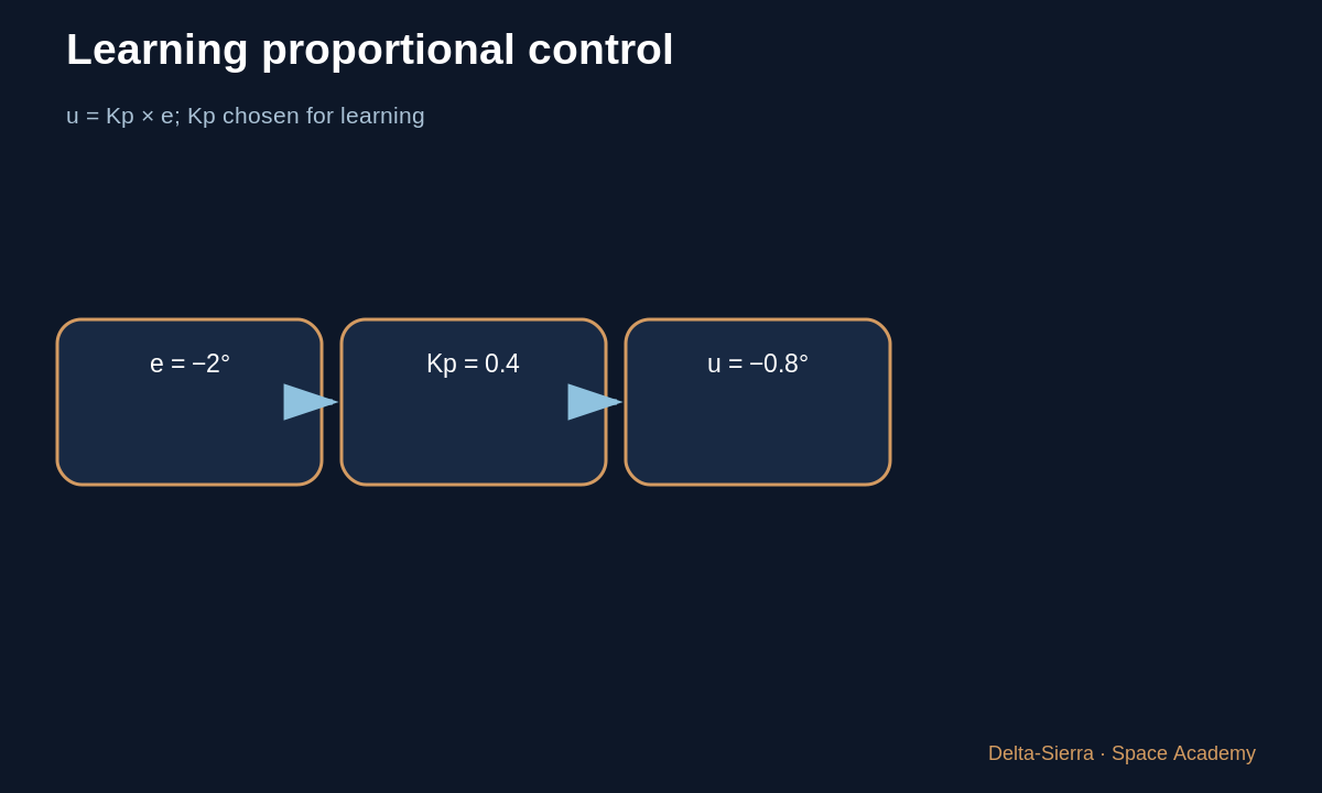
LEARNING ASSUMPTION: command = Kp × error with Kp = 0.4. Then command = 0.4 × (−2°) = −0.8°.
0.4 is not a SpaceX, Ariane, or NASA value. It is chosen solely to explain feedback. Real laws include dynamics, angular rates, filters, actuator constraints, and multiple nested loops.
4 — Why not command −2° of gimbal directly?
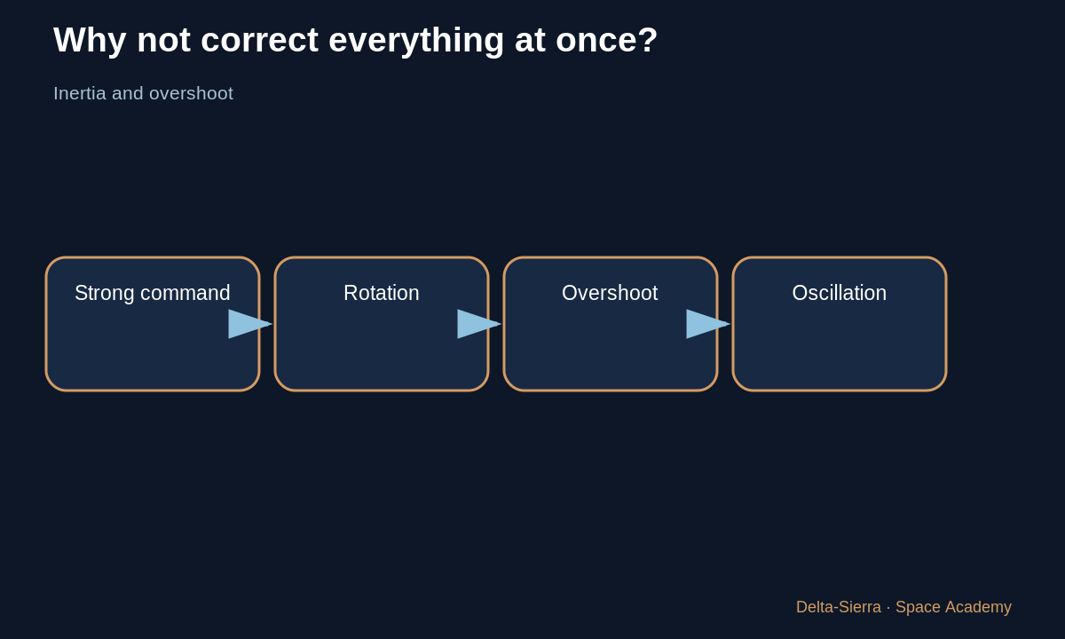
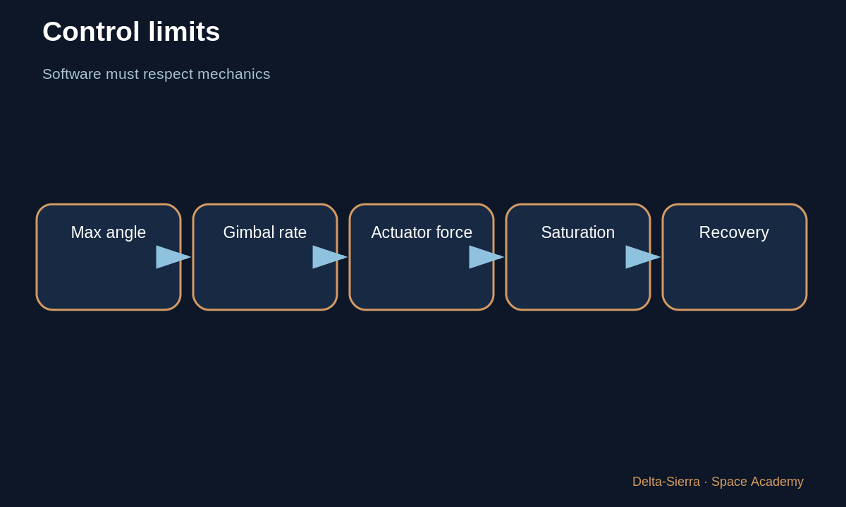
The engine acts on a vehicle with inertia. Too much command can overshoot, oscillate, or excite structural bending.
The controller must account for how the vehicle will continue rotating during and after the action. Angular rate is therefore often as important as angle.
5 — Sensors do not deliver perfect truth
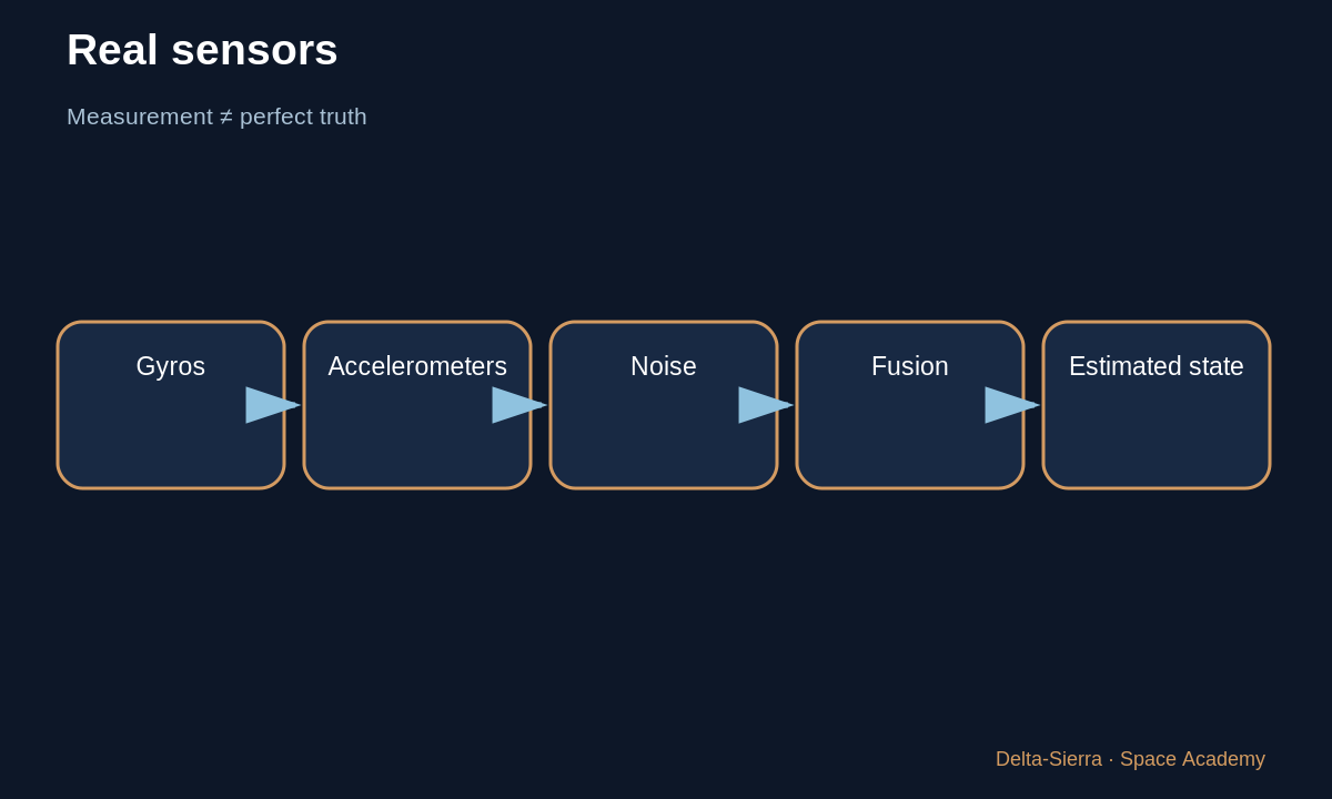
Gyros and accelerometers have bias, noise, and drift. Software combines measurements and maintains an estimate with uncertainty. Outliers must be detected before becoming large commands.
Redundancy alone is not enough: three sensors sharing the same systematic error can agree and still be wrong.
6 — The real system is a fast loop
Command changes gimbal, changing thrust direction and angular acceleration. Sensors observe the new state milliseconds later and the computer recalculates.
Loop stability is a full engineering discipline. Our −0.8° example is only the first conceptual step.
7 — Attitude measurement is not direct access to “truth”
An inertial unit measures quantities such as rotation and acceleration. Software combines these measurements over time to estimate vehicle state. Every measurement contains noise, bias and uncertainty, so the estimate can drift. Other references, when available, help correct or cross-check it.
The important word is estimate. An autonomous system does not possess perfect knowledge of its situation; it possesses a best estimate based on sensors, models and history. That estimate, not a magical truth, feeds the control loop.
8 — Why the 2° example is not a flight-control recipe
Our proportional controller is intentionally elementary. In a real vehicle, angle is only part of the problem: angular rate already tells whether the rocket is moving toward or away from the target, while flexible structural modes can be excited by aggressive commands. Engineers therefore use models and control laws tailored to the actual vehicle.
The 2° case is a window into the reasoning: define error, select a sign convention, apply a correction, observe response and repeat. Space Academy teaches the loop without publishing an operational flight-control law for a real launch vehicle.
8 — Three cases: how command changes when error changes
Example A — 2° error
In our teaching example, angular error e = 2° and proportional gain Kp = 0.4. The simplified command is u = Kp × e = 0.4 × 2 = 0.8 command unit. Kp is a coefficient chosen here to show that proportional command grows with error.
🎓 TEACHING ASSUMPTION: 0.4 is not a published SpaceX or Ariane flight gain.
Example B — halve the error
If the error is only 1° with the same Kp = 0.4, then u = 0.4 × 1 = 0.4. Halving the error halves this proportional component.
🧮 CALCULATED: the relationship is linear in this simplified model.
Example C — double the gain
With e = 2° but Kp = 0.8, u = 0.8 × 2 = 1.6. The same attitude error creates twice the command. Faster correction can be useful, but overly aggressive control may contribute to overshoot or oscillation; real gains are tuned with vehicle dynamics, delays, sensors, and actuators.
⚠️ APPROXIMATION: a real launch vehicle is not controlled by one proportional gain alone.
Error sign — command the correct direction
If e = −2° and Kp = 0.4, then u = −0.8. The negative sign is not a “bad value”; it indicates the opposite direction under the chosen sign convention.
📐 CONVENTION: positive and negative directions must be defined consistently across sensors, software, and actuators.
Exercises and answers
Error
Command 1°, measurement 1.7°. e = command − measurement.
Learning command
Kp = 0.5 and e = −0.7°.
Trap
Why must that gain never be presented as a Falcon 9 value?