Lesson compass
AM-08.06 — Optical navigation: using images, planets and terrain to locate yourself. The lesson starts with a concrete scene, defines every word and symbol, and only then introduces equations and mission decisions.
1 — Start from a concrete scene
Mars has no GPS constellation continuously giving a rover its position. Yet a camera can recognize the world around it. If software measures how rocks move through images as the rover drives, or matches a panorama to an orbital map, the image becomes a navigation measurement.
Optical navigation can be used during interplanetary cruise, near a body, during landing, or on the surface. The common principle is to turn pixels into geometry: angles, directions, relative motion, or terrain matches.
2 — Essential vocabulary before going further
None of these words should remain mysterious. A short definition is better than unexplained jargon.
- Optical navigation
- Estimation of position, velocity, or attitude from images and visual targets.
- Pixel
- Smallest element of a digital image. Its image position maps to a direction through camera calibration.
- Visual odometry
- Motion estimation by tracking visual features across images.
- Orbital map
- Image or model built from an orbiter and used as a global reference.
- Orthomosaic
- Geometrically corrected image mosaic representing terrain as seen from above.
- Registration / matching
- The process of aligning an observation with a known reference.
3 — See the system before calculating
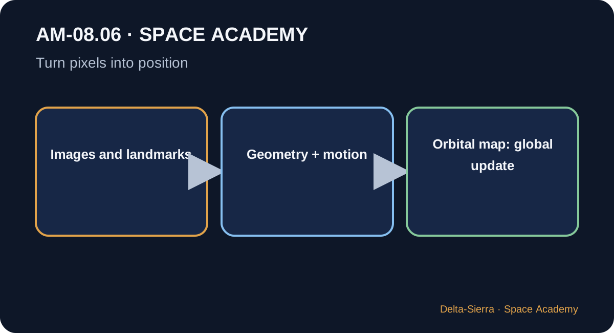
From pixel to direction
A camera is calibrated: focal length, optical centre, and distortion are known. An object’s image position can then be transformed into a line of sight from the sensor.
Track the terrain
By comparing successive images, software tracks visual features. Their apparent motion, combined with the camera model, estimates vehicle motion. Errors still accumulate gradually.
Return to an absolute map
Global localization compares a local view with a larger reference map. In February 2026, JPL reported Perseverance using Mars Global Localization to match Navcam panoramas with orbital imagery and update its location without human help.
4 — The formulas, only now
A formula is a compressed sentence. We unpack it before using it.
How to read it : “angle is approximately arctangent of x divided by f.” Here x is image-plane offset and f is focal length in a simple model.
Camera geometry converts image-plane displacement into angular direction. Real systems correct distortion and use two dimensions.
How to read it : “distance is approximately baseline divided by tangent of angle,” in a simplified triangulation geometry.
A known baseline between observations or cameras lets angular parallax provide depth information. Exact geometry depends on the setup.
5 — What the units tell us
Images are measured in pixels, but navigation ultimately produces angles in radians/degrees and distances in metres/kilometres. Pixel-to-angle conversion depends on calibration. A one-pixel accuracy therefore has no universal meaning without field of view and resolution.
6 — Three concrete demonstrations
Example 1 — Apparent motion
A rock moves from image column 600 to 640 between two frames.
image displacement = 640 − 600
image displacement = 40 pixels
Example 2 — Teaching triangulation
Two observing positions are separated by a 10 m baseline and a simplified geometry gives 5°.
tan(5°) ≈ 0.0875
distance ≈ 10 ÷ 0.0875
distance ≈ 114 m
Example 3 — Drift then global update
A rover uses visual odometry and accumulates 25 m uncertainty. A reliable match to an orbital map provides a new global reference.
before: local estimate + drift
terrain ↔ map matching
after: globally updated position
7 — Deepening: what the summary hides
Visual odometry and wheel slip
On a rover, wheel rotations alone are insufficient because wheels slip. Vision directly observes apparent terrain motion and helps resolve that ambiguity.
Feature-poor terrain
Uniform plains, dust, shadows, or lighting changes make matching harder. Navigation then needs to increase uncertainty or rely more heavily on other sensors.
Landing navigation
Algorithms can compare observed terrain during descent with a map to estimate position relative to hazards. It is the same family of ideas as surface localization, under much harsher speed and safety constraints.
Autonomy and onboard computing
The more a mission wants to localize without waiting for Earth, the more maps, camera models, computing power, and outlier-rejection software must be carried onboard.
8 — Why this matters for Mars
Mars surface operations involve long distances, obstacles, and radio delay that prevents continuous Earth driving. Visual navigation lets the vehicle understand its local surroundings.
JPL's 2026 Mars Global Localization result illustrates an important step: automatically match rover views to orbital imagery to reduce dependence on human localization updates.
9 — Common traps and bad intuitions
- Thinking a photo directly contains object distances.
- Confusing drifting visual odometry with absolute global localization.
- Forgetting optical calibration and distortion.
- Accepting a terrain match without plausibility checks.
- Assuming lighting, dust, and shadows do not affect vision.
10 — Guided exercises and answers
Question : A feature moves 25 pixels right. What is known for certain?
Question : Why does visual odometry drift?
Question : Why can an orbital map act as a global update?
11 — What I should be able to explain at the end
- Define optical navigation, pixel, visual odometry, and registration.
- Explain how a calibrated camera produces a line of sight.
- Distinguish image motion from physical motion.
- Explain why visual odometry drifts.
- Describe Mars Global Localization without calling it Martian GPS.
12 — NASA / JPL sources for further study
Primary institutional sources used to check concepts and orders of magnitude.