1 — The concrete scene
From far away an Earth-Mars vehicle looks like one object. In reality structure, power, thermal, avionics, communications, GNC, propulsion and payload must work together, sometimes for months.
The key point is never to isolate this subject from the rest of the spacecraft. A local change often moves mass, power, heat, data, software, testing or risk elsewhere in the system.
2 — Essential words, explained before using them
Before calculating, we define every word that will be used next. The goal is for the symbol to come after the idea, never before it.
- Bus
- Shared support functions enabling the mission.
- Payload
- What the vehicle carries to accomplish its purpose.
- Subsystem
- Organised family of functions and hardware.
- Interface
- Boundary exchanging data, power, heat, loads or matter.
- Requirement
- Verifiable condition imposed on design.
- Margin
- Reserve between need and capability.
3 — See the architecture before calculating
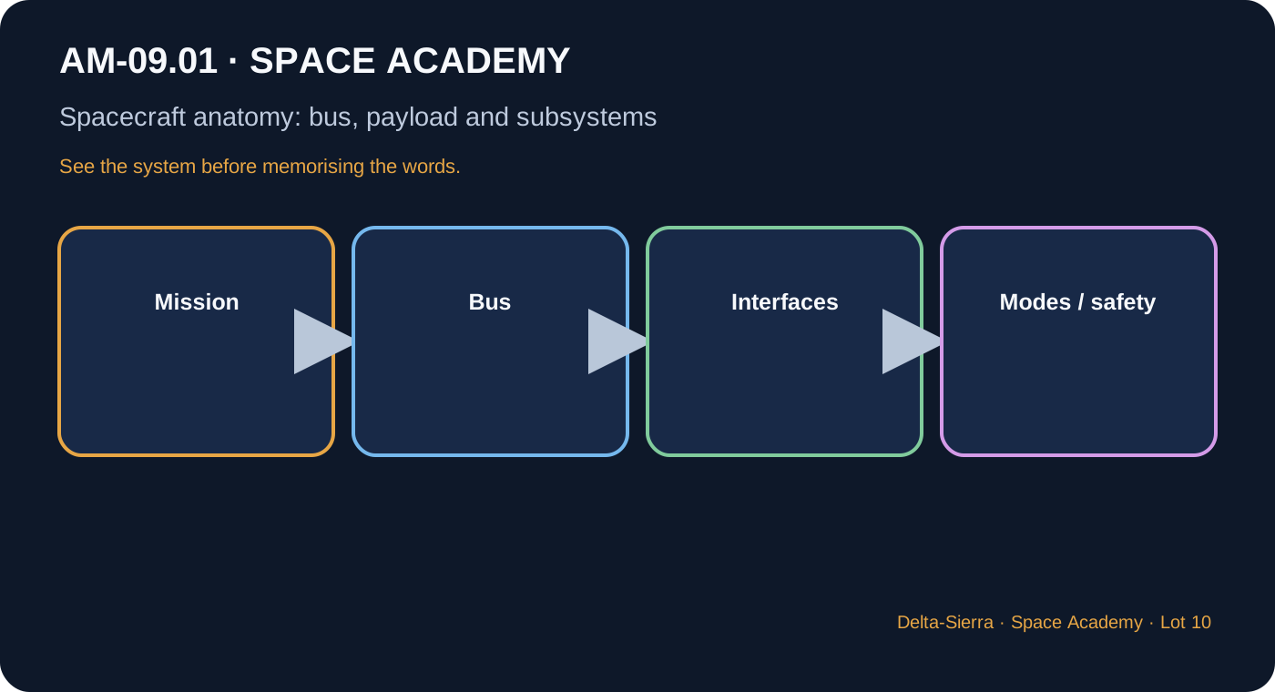
Mission drives architecture
Start from functions, environments and duration before boxes.
Budgets connect teams
Mass, power, data and heat are shared.
Modes change needs
Cruise, manoeuvre, communication and safe mode activate different loads.
Redundancy needs independence
Two units sharing power or software can fail together.
4 — Formulas, only when they answer a question
A formula is useful only if we know which question it answers, what every symbol means, and which units must be used.
How to read it : total mass equals the sum of item masses
Σ means add every item in the budget.
How to read it : total power equals sum of active loads
The sum must be made by operating mode, not blindly across all hardware.
5 — What units and margins mean
kg, W, Wh/J, bit/s and temperatures remain separate: different physical quantities are never added.
6 — Three concrete demonstrations, calculated step by step
Mass budget
420 kg structure + 180 kg avionics + 260 kg power + 640 kg payload.
420+180+260+640 = 1,500 kg
10% reserve = 150 kg
Total with reserve = 1,650 kg
Two power modes
Cruise 900 W; manoeuvre adds 600 W.
Cruise = 900 W
Manoeuvre = 1,500 W
Check generation and distribution at peak.
Electrical-thermal interface
Useful computer power 80 W, converter 90%.
Upstream = 80/0.90 = 88.9 W
Loss = 8.9 W
Those 8.9 W become local heat.
7 — Deepening: what the simplified diagram hides
Functional architecture
Which functions must exist?
Physical architecture
Which hardware performs them?
Hidden dependencies
A heater depends on sensor, software, relay and power.
Degraded modes
Decide what stays alive when capability falls.
Evidence
Analysis, inspection, test and demonstration close the loop.
8 — Application to an Earth-Mars spacecraft
On an Earth-Mars transit, long duration turns a small weakness into cumulative risk: ageing, drift, consumption, cycles and maintenance become as important as nominal performance.
Communication delay forces the vehicle and possibly the crew to diagnose and reconfigure locally. Design must therefore remain observable, understandable and testable in degraded modes.
9 — Reference dossier: what a real project must still consider
This section deliberately goes beyond the introductory calculation. It connects the concept to interfaces, failures, testing, duration and maintenance so the lesson can serve as a reference chapter rather than a revision card.
From mission need to architecture
A spacecraft should not be designed by first choosing a battery, computer or engine. Start with the mission: payload, destination, duration, navigation accuracy, communications, environment, autonomy, safety and possibly crew. These needs become measurable requirements. Functional architecture describes what the vehicle must do; physical architecture later assigns those functions to real hardware. Keeping those two levels separate prevents the mission from being forced into a collection of preselected boxes.
Bus and payload are useful but imperfect boundaries
The bus is not necessarily one physical object. It groups common support functions that make the mission possible. Payload is what directly accomplishes the primary objective. On an Earth-Mars vehicle the boundary can become ambiguous, so the important issue is not the label but clear interfaces, ownership, budgets and modes. A poor boundary can hide a critical dependency.
Budgets are contracts between subsystems
Mass, power, energy, volume, heat rejection, data rate, propellant and computing time are shared resources. A budget is therefore not an end-of-project spreadsheet. It prevents one team from optimising locally at the expense of the vehicle. A heavier instrument affects structure and propulsion; a stronger transmitter affects power and thermal control. Margins must be defined rather than assumed.
Operating modes change everything
Launch, cruise, high-rate communications, manoeuvres, charging, science, emergency and safe mode do not activate the same equipment. Adding every load can over-size a system, while using only an average can hide an impossible peak. A mode-function matrix makes required loads, allowed shutdowns, redundancy and transitions explicit. For Mars, surviving a long degraded mode may matter more than a short peak capability.
Redundancy needs real independence
Two computers sharing one converter are both lost if that converter fails. Identical software can share the same design defect, and co-located sensors can share the same environmental hazard. Robust design therefore considers common-cause failures and may separate power feeds, data paths, sensors, locations or technologies.
Design for maintenance before departure
Mars missions change the value of accessibility, spares, tools, connectors, procedures and fault isolation. A compact design may save mass yet make repair impossible. A modular design may cost mass but improve maintainability. The correct trade depends on mission duration, crew, autonomy and consequence of failure.
Evidence matters as much as architecture
A neat diagram is not proof. Important requirements need verification by analysis, inspection, demonstration or test, interfaces must be exercised, degraded modes must be tested and margins must be recalculated after changes. Validation asks a different question: even if the design meets its requirements, does it actually satisfy the mission need?
10 — Common traps and bad intuitions
- Confusing bus with shell.
- Adding powers without a mode.
- Calling common-cause equipment redundant.
11 — Guided exercises
Question : What question comes before choosing hardware?
Question : Why is a nominal result insufficient?
12 — What to remember
- Explain the topic in simple words before symbols.
- Connect at least four interfaces with other subsystems.
- Redo the three numerical examples without reasoning gaps.
- Identify at least three limits or failure modes absent from the ideal calculation.
13 — NASA sources for further study
Primary institutional sources used to check the lesson structure. Teaching-number examples are identified as such.