1 — The concrete scene
During launch a structure sees acceleration, vibration and shock. In cruise loads drop but alignment and thermal expansion still matter.
The key point is never to isolate this subject from the rest of the spacecraft. A local change often moves mass, power, heat, data, software, testing or risk elsewhere in the system.
2 — Essential words, explained before using them
Before calculating, we define every word that will be used next. The goal is for the symbol to come after the idea, never before it.
- Load
- Applied demand: tension, compression, bending, vibration or shock.
- Stress
- Force divided by area.
- Stiffness
- Ability to limit deformation.
- Natural frequency
- Natural vibration frequency.
- Resonance
- Amplification near a natural frequency.
- Buckling
- Loss of stability of a compressed member.
3 — See the architecture before calculating
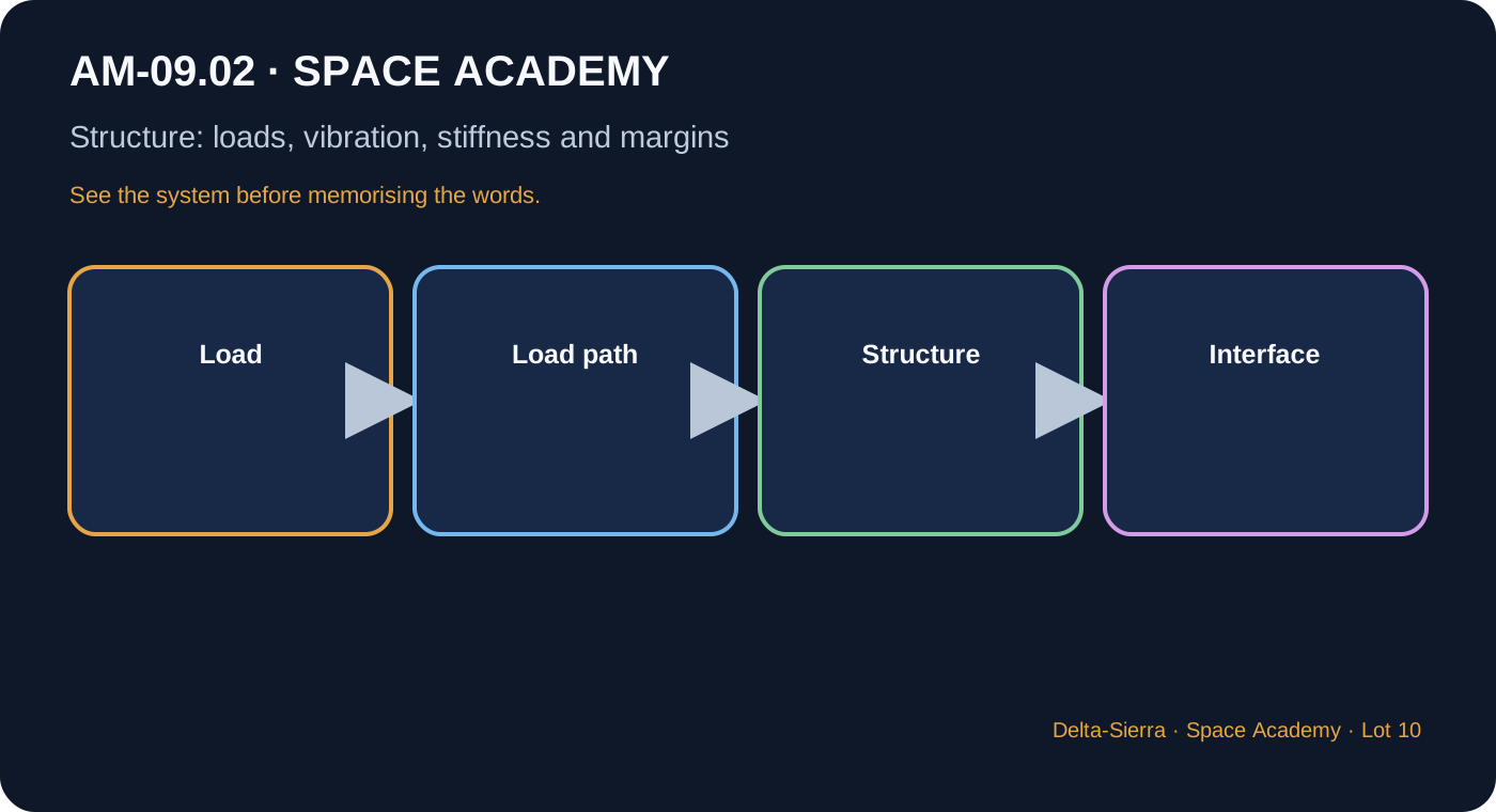
Load path
Load must travel continuously to supports.
Stiffness before failure
An instrument can lose alignment without material breaking.
Vibration
Natural modes interact with launcher or mechanisms.
Thermal
Different materials expand differently.
4 — Formulas, only when they answer a question
A formula is useful only if we know which question it answers, what every symbol means, and which units must be used.
How to read it : sigma equals force divided by area
Simple average stress; geometric details create concentrations.
How to read it : force equals mass times acceleration
First inertial load estimate, not a complete vibration model.
5 — What units and margins mean
N for force, Pa or MPa for stress, Hz for frequency, m or mm for deformation.
6 — Three concrete demonstrations, calculated step by step
Inertial load
50 kg at 6 g, g=9.81 m/s².
a=58.86 m/s²
F=50×58.86=2,943 N
≈2.94 kN
Average stress
20 kN through 400 mm².
400 mm²=0.0004 m²
σ=20,000/0.0004
σ=50 MPa
Expansion
2 m aluminium, ΔT=60 K, α=23×10⁻⁶/K.
ΔL=αLΔT
=23×10⁻⁶×2×60
=2.76 mm
7 — Deepening: what the simplified diagram hides
Primary / secondary
Primary structure carries critical loads; secondary supports equipment.
Buckling
A member can lose stability before simple material strength.
Fatigue
Cycles accumulate damage.
Modal tests
Tests correlate vibration models.
Interfaces
A small fastener can be more critical than a large panel.
8 — Application to an Earth-Mars spacecraft
On an Earth-Mars transit, long duration turns a small weakness into cumulative risk: ageing, drift, consumption, cycles and maintenance become as important as nominal performance.
Communication delay forces the vehicle and possibly the crew to diagnose and reconfigure locally. Design must therefore remain observable, understandable and testable in degraded modes.
9 — Reference dossier: what a real project must still consider
This section deliberately goes beyond the introductory calculation. It connects the concept to interfaces, failures, testing, duration and maintenance so the lesson can serve as a reference chapter rather than a revision card.
Space structure is more than static weight
Spacecraft experience acceleration, vibration, acoustic, pressure, manoeuvre and thermal loads. During launch, even a light box can create large forces because acceleration multiplies inertia. Loads travel through equipment, fasteners, panels, frames and the launch adapter. A small insert or bolt may therefore control a much larger assembly. Start by identifying load paths, not by simply making panels thicker.
Strength, stiffness and stability are different
A part can remain unbroken yet become unusable. Excess deformation can spoil antenna pointing or jam a mechanism. Stiffness controls deformation and natural frequencies; stability includes buckling, where a compressed shell may suddenly deform before the material reaches a simple strength limit. Margins must therefore be assessed for each relevant failure mode.
Why launch vibration matters
Launch vibration and acoustics excite structural natural frequencies. Excitation near a mode can amplify response through resonance. Modal models and tests are used to check real frequencies and damping. Even a modest mass change can move a natural frequency, so mechanical configuration must stay controlled through integration.
Fatigue makes repeated small loads important
Failure can grow from repeated cycles rather than one extreme load. Thermal cycles, pressure cycles, mechanisms and vibration can initiate and propagate cracks. Long Mars missions increase some cycle counts, making stress concentrations, manufacturing quality and inspection important.
Thermal expansion becomes structural
Different materials expand differently. Rigidly joining aluminium, composites, optics and electronics can create thermal stress or misalignment. Flexible mounts, controlled clearances or compatible materials are therefore used. Structural analysis and thermal analysis cannot be isolated from each other.
A positive margin is not automatic safety
Every margin depends on assumptions about loads, material properties, factors, geometry, temperature and manufacturing scatter. A large numerical margin is meaningless if the load case is wrong. Data provenance and combined worst cases matter.
Test and model correlation
Finite-element analysis remains a model. Vibration tests, static tests, modal measurements and inspection compare reality with prediction. Differences are used to update the model before extrapolation. This analysis-test-correlation loop turns a theoretical model into a trusted engineering tool.
10 — Common traps and bad intuitions
- Confusing strength and stiffness.
- Using F=ma as a full vibration environment.
- Ignoring buckling and stress concentrations.
11 — Guided exercises
Question : What question comes before choosing hardware?
Question : Why is a nominal result insufficient?
12 — What to remember
- Explain the topic in simple words before symbols.
- Connect at least four interfaces with other subsystems.
- Redo the three numerical examples without reasoning gaps.
- Identify at least three limits or failure modes absent from the ideal calculation.
13 — NASA sources for further study
Primary institutional sources used to check the lesson structure. Teaching-number examples are identified as such.